
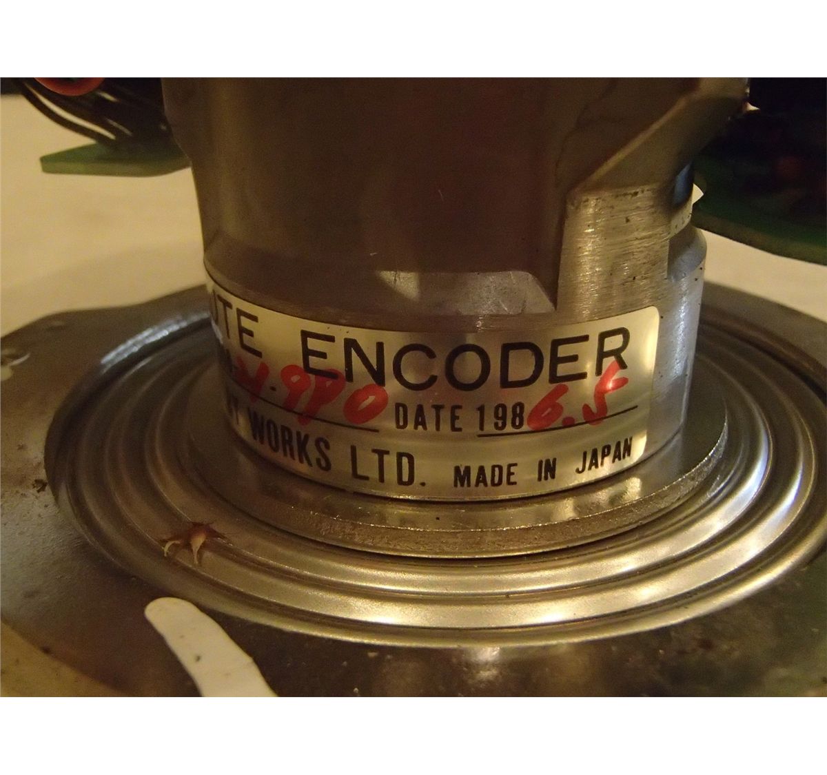
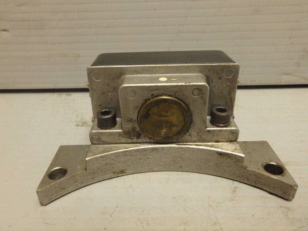
Okuma Encoder M/N ERTC1D, TS2670N1E1
Rotary Encoder - Example #1. We'll now go through a simple example to introduce you to the use of a rotary encoder. In this example we will: Determine the absolute position of the encoder going from -100 to 100. Each point is equal to one click in the encoder. If you continue rotating past +100 or past -100, the code will max out the count.
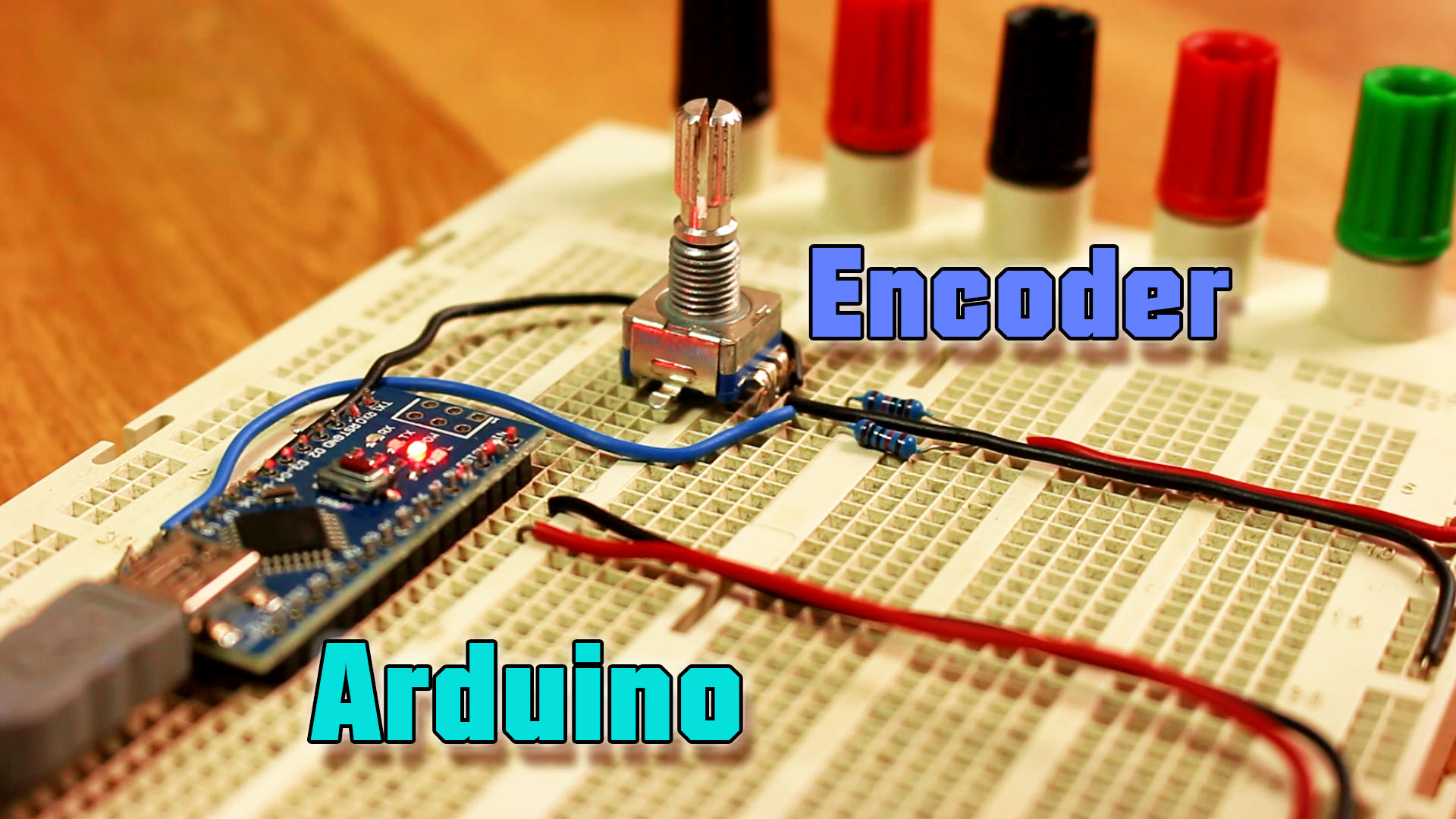
Arduino rotary encoder tutorial with interruptions
Each detent generates a digital signal that's used by the Arduino to determine the position of the encoder knob. The number of detents per rotation defines the resolution of the encoder. Encoders with more detents have a greater resolution. The Keyes KY-040 rotary encoder used in this article has 20 detents in a full rotation.

1005801102281 Okuma Absolute Encoder ERJE7200D Meijdam
Rotary Encoder Arduino Code Explanation: First we will import the servo motor library in the Arduino code if we not include the library the code will not work. Then define the clk and data pin at 3 and 4 respectively. Define the switch pin at 5. We will set the counter value at 90. State and lstate variables are used to store the state.
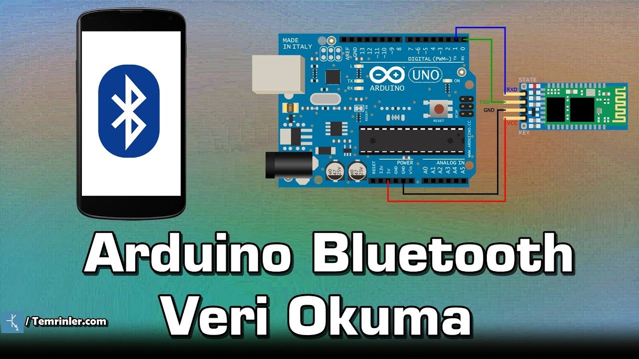
Arduino Bluetooth veri okuma YouTube
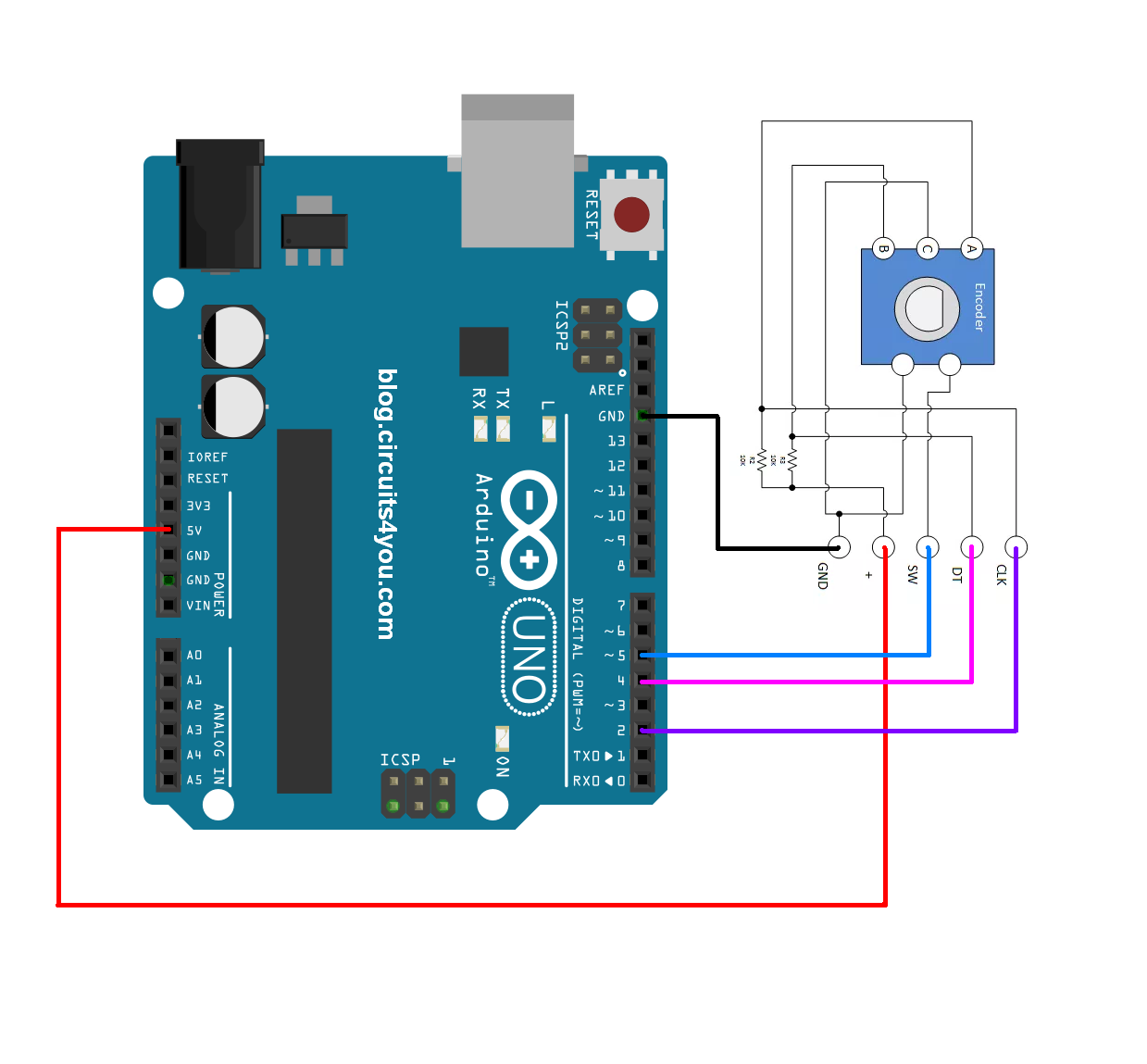
Step 1: Wiring. Connect the Rotary Encoders Module to the Arduino board as follows: Connect the module's CLK (Clock) pin to a digital pin on the Arduino (e.g., D2). Connect the module's DT (Data) pin to another digital pin on the Arduino (e.g., D3). Connect the module's SW (Switch) pin to a digital pin on the Arduino (e.g., D4).
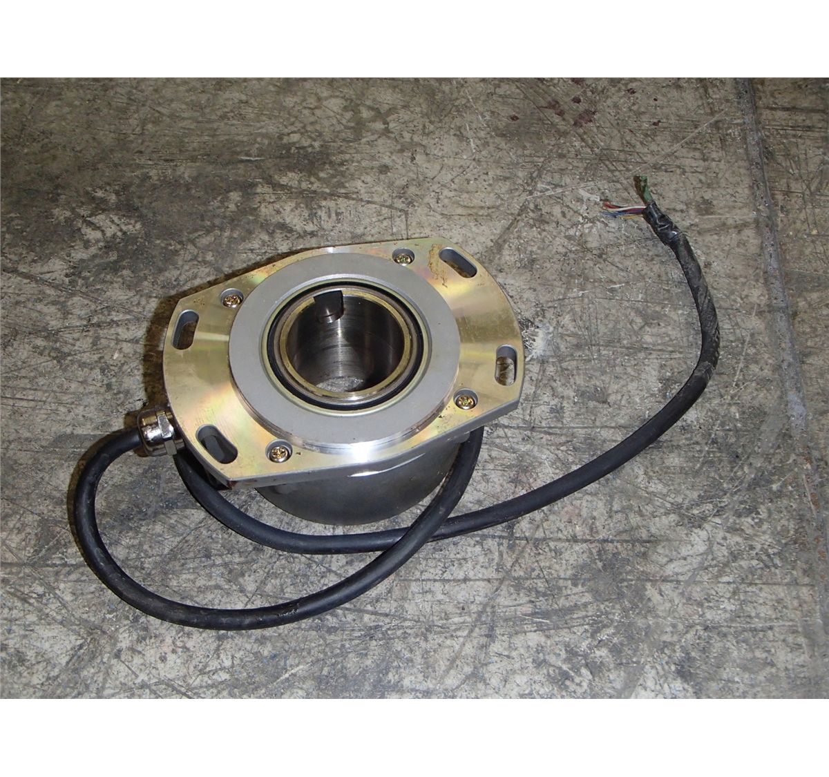
Okuma Absolute Encoder, Type F BTM Industrial
Rotary Encoder Module Pinout. The Rotary Encoder Module has 5 pins; those are GND, + (VCC), SW (Switch), DT, and CLK. All the pins of this sensor module are digital, except VCC and Ground. The Pinout of a Rotary Encoder Module is shown below: GND is the ground pin of the Rotary Encoder Module and it should be connected to the ground pin of the.
Arduino Rotary Encoder Module KY040
A rotary encoder, also called a shaft encoder, is an electro-mechanical device that converts the angular position or motion of a shaft or axle to analog or digital output signals. There are two main types of rotary encoder: absolute and incremental. The output of an absolute encoder indicates the current shaft position, making it an angle.
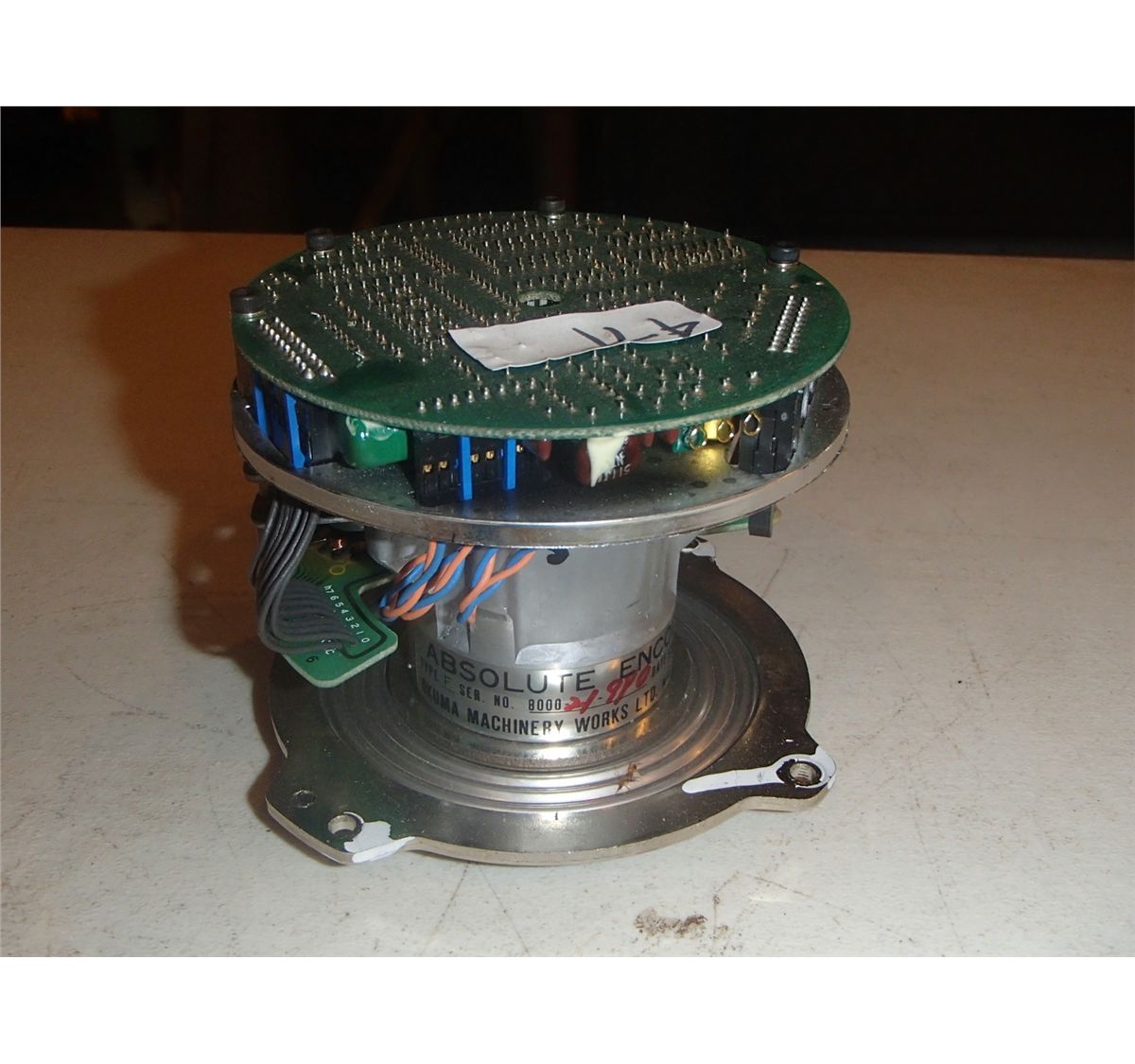
Okuma Absolute Encoder, Type F BTM Industrial
Encoder Signal Input/Output Counts quadrature pulses from rotary & linear position encoders. Encoder counts pulses from quadrature encoded signals, which are commonly available from rotary knobs, motor or shaft sensors and other position sensors. Author: Paul Stoffregen Maintainer: Paul Stoffregen Read the documentation Go to repository

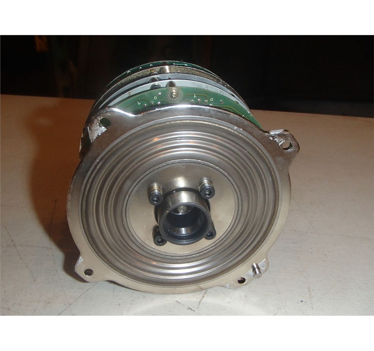
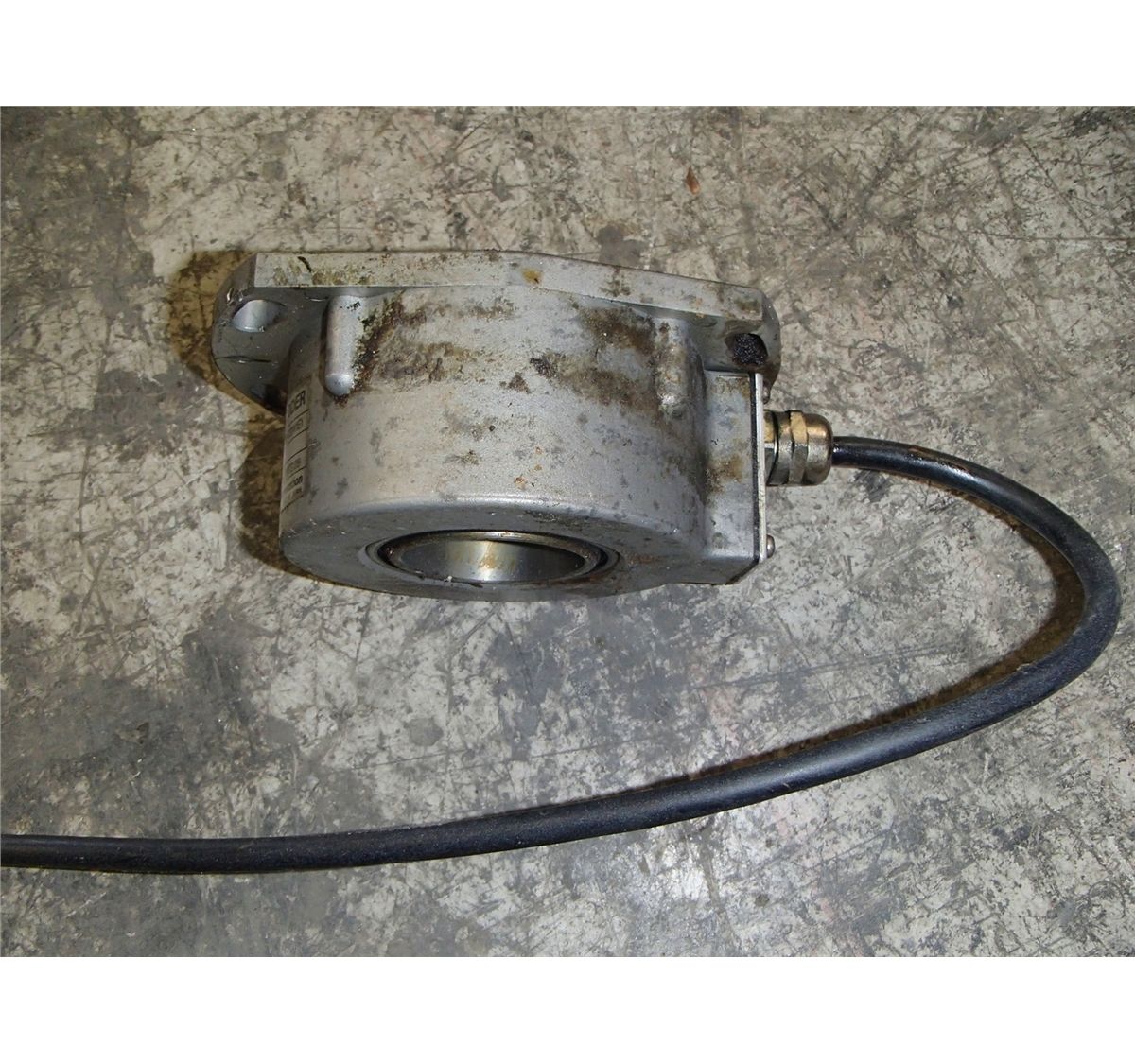
Okuma Absolute Encoder BTM Industrial
Rotary encoders are classified into two types: absolute and incremental. The absolute encoder reports the exact position of the knob in degrees, whereas the incremental encoder reports the number of increments the shaft has moved. The rotary encoder used in this tutorial is of the incremental type. Rotary Encoders Vs Potentiometers
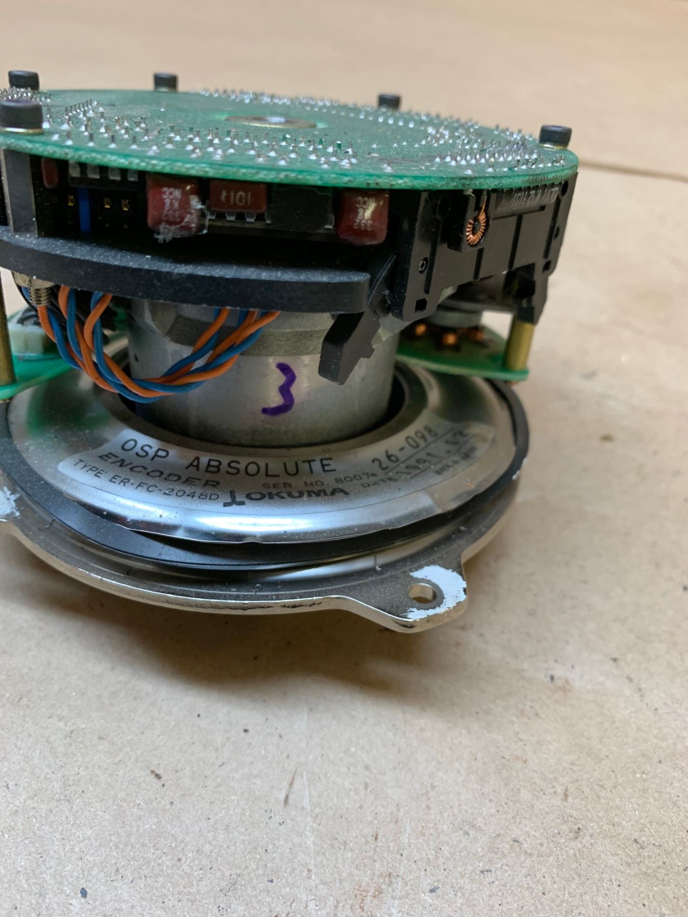
Okuma 26098 Encoder BTM Industrial
Free Shipping Available On Many Items. Buy On eBay. Money Back Guarantee! But Did You Check eBay? Check Out Arduino Encoder On eBay.

Okuma Encoder M/N ERTC1D, TS2670N1E1 BTM Industrial
There are two main types: Incremental encoder: which generates pulses to measure relative change Absolute encoder: which provides a unique digital code for each position, making them ideal for precise positioning even after power loss. This guide is about the incremental encoder. Rotary Encoder Module Pinout
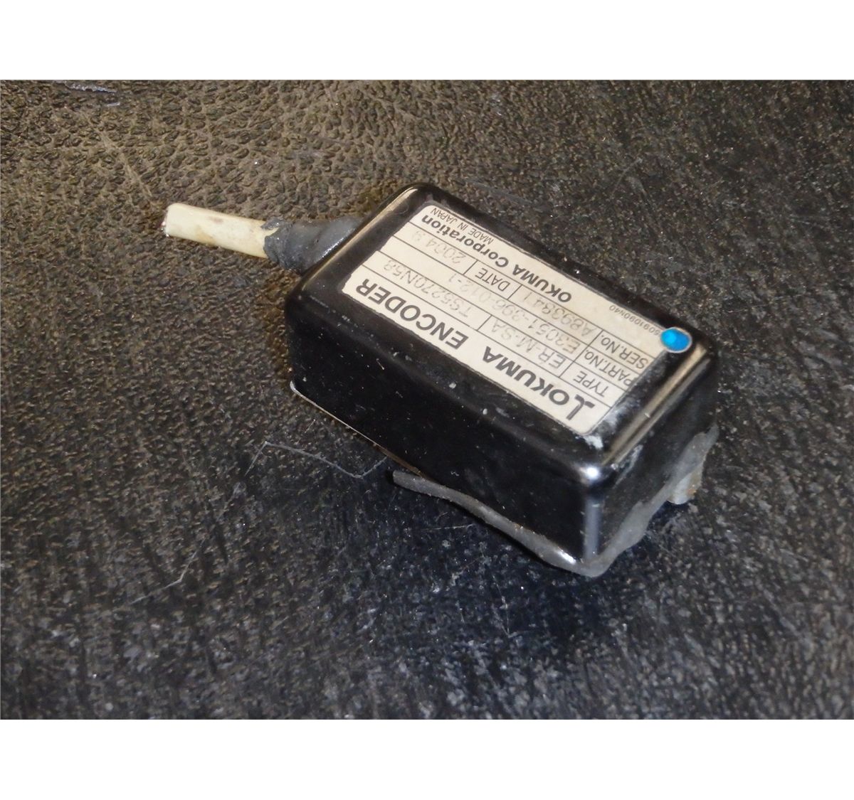
Okuma Encoder, M/N E30513960121, Type ERMSA
Arduino ile Enkoder Uygulaması Kodu Nasıl Yazılır?Enkoder okumak ve yazmak için interrupt uygulaması.Seri Port uygulaması ile yazdığımız kodun debug yapısı.İ.
Okuma Absolute Encoder, Type F BTM Industrial
Software Configurations and Arduino Library Code. Step 1: Install the Encoder Library in the Arduino IDE by hovering your cursor to Sketch -> Include Library -> Manage Libraries. Step 2: Search for the encoder in the pop-up window and find Encoder by Paul Stoffregen, choose the Version 1.4.1 and click install.
OKUMA ENCODER ERMSA
Step 1: Pulse Flow of Rotary Encoder The pulse flow generated by the following rotary encoder is like the picture above. Ask Question Step 2: Pinout of Rotary Encoder Explanation: GND --> GND + --> +5V SW --> button of rotary encoder when pressed DT --> Data CLK --> Data 2
Okuma Encoder M/N ERTC1D, TS2670N1E1 BTM Industrial
Connect the rotary encoder to the breadboard. Place the two 10 kΩ resistors R1 and R2 from A and B to 5V. Place the two 10 kΩ resistors R3 and R4 from A and B to the Arduino digital pins 10 and 11, respectively. Place the 0.1uF capacitors (C1 and C2) as shown in the schematic to debounce the encoder signal. Connect point C to ground.

OKUMA ENCODER ERMB7200D A005801D CNC Electronic System
The circuit is so simple. You will need: • An ATMEGA328P based Arduino, such as the Uno, Pro Mini or Nano. • A mechanical (as opposed to optical) quadrature rotary encoder - this is the most common kind so don't worry too much if it isn't specified. eBay and Aliexpress listings will often mention Arduino in the description and this is a good indicator that one is suitable.
Okuma Encoder M/N ERTC1D, TS2670N1E1 BTM Industrial
As stated, the rotary encoder has 2 coding pins that are either HIGH (1) or LOW (0). If you treat the pins as binary, you can read them as 00, 01, 10, or 11 (sequence the encoder outputs while spinning clockwise is 00, 01, 11, 10). If you have a reading of 01, the next reading can either be 00 or 11 depending on the direction the knob is turned.